AC-3 Audio Codec

Introduction
AC-3 audio coding scheme is developed by the Dolby
Company. Dolby Digital,
the audio standard used in film industry, DVD,
multimedia, HDTV, Dolby Surround Digital(the audio standard used in Home
Theater System (HTS)), and Dolby Net(used in the internet environment),
all refer to the same kernel -- the AC-3 audio coding technology. To feed
these quite different demands of all these different areas, the target
bit-rates of AC-3 ranges from 32k bps to 640k
bps.
AC-3 allows encoder to provide special bit stream information
for decoder to reconstruct the original "audio environment" of that audio
sequence. For example, a dialogue parameter is used for sound level uniformity
if several different AC-3 sequences are needed to playback. A room type
parameter allows decoder to simulate the surround effect of the original
space. Parameters of dynamic range control and the sound level compression
are also used for specific playback.
AC-3 is a perceptual audio coder (PAC), that is, AC-3 uses human
psycho-acoustic features to "mask" the inaudible audio signals, so the
bits are saved for really important signals. Up to 5 full-bandwidth channels
and one subwoofer channel (cutoff at 120Hz) can be contained in an AC-3
bitstream (this is so-called 5.1 channels). The time-frequency transform
used in AC-3 is Analysis/Synthesis Filter Bank with Time Domain Aliasing
Cancellation. A parametric bit allocation process is applied in AC-3, so
flexibility and efficiency can be achieved at the same time. With sophisticated
psycho-acoustic model and the decorrelation between neighbor frequencies
and different channels, AC-3 provides low-bandwidth but high quality perceptual
audio sound.
Psycho-Acoustic
Model
AC-3 designed a parametric psycho-acoustic model such that flexibility,
efficiency, and low bandwidth requirement can all be achieved in the bit
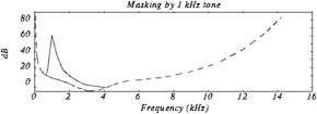
allocation process. When considering the masking
effect, AC-3 only adopts the upward spectral masking effect since
the spectral spreading function is skewed toward the high frequency side
(Fig. 1) and the temporal masking is not so important and is considered
inapparently in other processes of coder.
Figure 1: The spectral masking curve (1kHz, 60dB)
The different behaviors of tonal and non-tonal signals are not separated
for simplicity and efficiency; instead, AC-3 compares signals with a given
threshold. Signals above the threshold are given more bits. AC-3 takes
quantization into account so that the distortion due to signal level loss
is inaudible. Coupling strategy is used to take advantage of the insensitivity
to high frequency of the HAS localization. Coupling is not combined into
the psycho-acoustic model in AC-3.
Different banding structure and psycho-acoustic model can also
be used in this model with some overheads in the encoder. Encoder calculates
both the original masking curve and the new masking curve, packing the
difference in the bit stream. Decoder decodes the difference and adds it
to the calculated original masking curve.
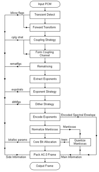
Six steps are contained in the bit allocation process. All the
operations needed are only addition, maximum, shift, and table-look-up
in all these six steps.
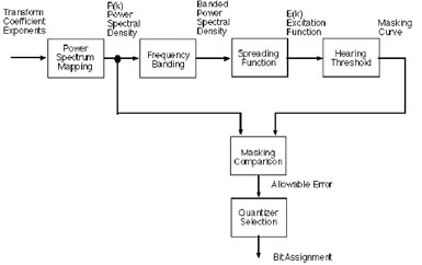 Figure 2: The block diagram of AC-3 bit alocation process
Subband
Filter Bank in AC-3
In PAC encoders, a "block" of audio signals must be windowed, and
passed through an analysis filter. With the filtered data, the bit allocation
process can understand the frequency behavior of this audio block and decide
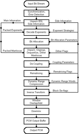
to what detail should one coefficient be coded. On decoder side, the frequency
data would be reversely windowed, and passed through a synthesis filter.
Then, the reconstruction of the time-domain data would be accomplished
by the final overlap-and-add process.
In this analysis/synthesis filter bank structure, error occurs
because of the filters is not perfect; sidelobes always introduce alias.
Error also introduced because of quantization due to bit allocation. If
quantization error is ignored, Perfect Reconstruction
(PR) does really exist. Frequency Domain Aliasing
Cancellation (FDAC) and Time Domain Aliasing
Cancellation (TDAC) filter bank structures are the most commonly
used. Alias in FDAC and TDAC are both canceled after the final overlap-and-add
process. In FDAC, the alias due to the analysis filter is compensated in
the frequency domain, i.e., the high frequency component of low band is
canceled by the low frequency component of high band. TDAC compensates
the alias in the time domain, i.e., the alias of the previous block is
canceled by the alias of current block.
AC-3 Audio
Codec
 |
Flow charts of AC-3 encoder and decoder |